4.15 - Listening Tips
4.15.1 - AM Carrier Interpretation
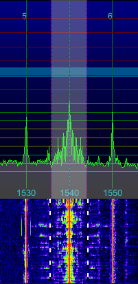
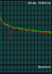
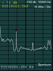
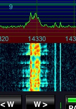
1540 KHz, Strong
About 100% modulation
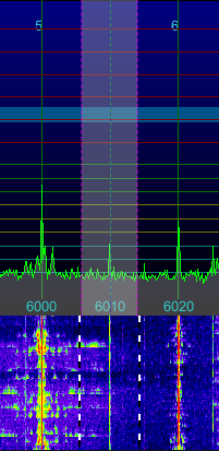
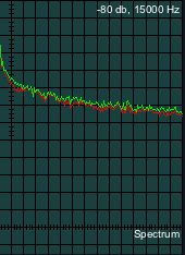
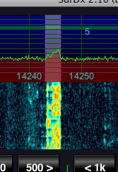
6010 KHz, Weak
Modulation Unknown
On the main spectrum, an AM carrier typically appears as a central peak within the sidebands carrying the audio transmitted with the carrier. At 100% modulation, the sidebands at the frequency of the strongest spectral component will reach 50% of the height of the carrier. This means that an AM mode radio transmission that is very strong will look like the image on the left when the signal is being 100% modulated.
One question that comes up quite often is "Why do I see AM carriers with no modulation?" The answer is found in the fact that 100% modulation only produces sideband amplitudes that are 50% of the carrier height; if the station is weak enough that it is halfway, or more than halfway, submerged beneath your noise floor, then all its sidebands are below the noise floor as well. So it looks — and sounds — just like a carrier with nothing going on. A better antenna might bring the sidebands above the noise floor, so might a change in propagation, or the station's transmitter power.
An example of such a weak signal is shown at the right; This station might have been transmitting silence, or very loud music — there's just no way to tell. The sidebands are below the noise floor, so all we see is the carrier, mute evidence that there is, in fact, a station there, but that perhaps we need to go antenna shopping. Or turn off all the nearby electronics and lights that are contributing to the noise level at our antenna. Sometimes that's enough. But you really can't beat improving your antenna system(s.) The best thing, of course, is to do both. Personally, I went so far as to build a small trailer with a shortwave listening setup in it and its own antenna that I can pull out into the country, far from the nearest electrical wiring. No man-made (QRN) noise at all, but the antenna... well, let's just say I wish it were better.
Because  AM audio is typically stronger in the bass frequencies, and weaker it approaches higher frequencies, one of the consequences of weak signal reception in AM is the highs fall below the noise floor before the low frequencies do. Because of this, you can reduce the demodulator bandwidth without losing signal; all you are doing is cutting out the noise, as long as you don't go too far. Observe the spectrum carefully to determine just how much of the AM sidebands you are receiving, as opposed to those that are submerged beneath the noise floor.
4.15.2 - Wideband FM
If you have an SDR that can sample at 180 KHz or more, SdrDx can receive wideband broadcast WFM in high fidelity. This is typically found in the range of 88 MHz to 108 MHz, also available at the 10.7 MHz IF mixer output of many classic WFM tuners, which puts WFM capability in range of many SDRs that are nominally only HF-capable.
At 180 KHz, you can receive WFM mono or stereo, as well as the RDS data signal. This is classic narrow-band. The FCC (in the US) requires that broadcasters transmit primary channel modulation that does not exceed +/- 75 KHz from the carrier frequency.
A rule of thumb known as Carsons Rule predicts the bandwidth occupied by the significant sidebands of an FM signal, based on the maximum modulation frequency and its corresponding modulation index:
B = 2 fm(m+1) = 2( δmax + fm)
Commercial monophonic FM broadcasting without SCA or Stereo subcarrier uses a maximum deviation of 75 KHz and a maximum modulating frequency of 15 KHz. Substituting these values into Carsons Rule:
B = 2*(75+15) = 180 KHz.
When the stereo pilot, stereo subcarrier, RDS / RDBS and / or SCA and / or SCB signals are added to the WFM carrier, the main WFM broadcast signal must be reduced in amplitude in order to ensure that the maximum modulation limit of 75% is not exceeded; this keeps the bandwidth requirements down around 180 KHz. 200 KHz is conservative in terms of catching everything, but it can also catch bleedover from excessively modulated signals on adjacent channels.
Consequent to these issues, for the narrowest safe bandwidth on an WFM signal where you have stereo turned off, I suggest 180 KHz.
4.15.2.1 - Auto-Stereo and Forced Monophonic
When receiving in mode, you can select , which, when illuminated, forces monophonic reception, which reduces noise considerably on weaker stations. When is off, SdrDx will switch into WFM Stereo mode any time the signal is strong enough. When is the current setting, the  ST indicator illuminates any time a sufficiently strong stereo signal is detected.
4.15.2.2 - FM Stereo Reverse
You can swap the contents of the left and right channels by turning on the button. This is only useful when receiving an WFM stereo signal.
4.15.2.3 - FM High-Blend
High Blend is available via the control. →Right-click opens the High Blend settings. I prefer 1986 Hz crossover, and +211 Hz overlap, but I have old ears. Set to taste. You can obtain quite a wide range of control; the objective, at least traditionally, is to make a noisy station sound less noisy, while a strong station should not sound much different at all.
High Blend operates by mixing a monophonic signal containing the high frequencies, where a great deal of noise can exist, with stereo signals containing the lower frequencies, where noise is generally less of a problem. The controls allow you to set where the crossover between the low and high frequencies occurs, and how much overlap there is between the two. As these are created with filters, and as the filter slopes vary with frequency, different crossovers will require different overlaps for the most even response.
High Blend off
High Blend on
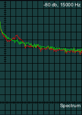
Bad overlap
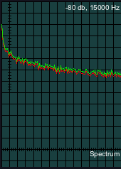
The control dialog accessed with →Right-click offers two controls. One is crossover point; the other is overlap. Before you open this dialog, select the scope mode, then →Right-click . This causes SdrDx to apply the filter to the right channel, and display (in the scope) spectra of the unfiltered right channel next that of the filtered right channel. One scope trace is red, one is green.
Now turn on the noise generator; when , it generates pink noise; noise that drops in amplitude as the frequency goes up. When , it generates white noise, which is noise that has equal amplitude at all frequencies. Use the signal source you find most intuitive. I prefer pink.
Enhance averaging first, ( →Right-click ), set it to about .16; this will reduce high speed variations in the waveform, and you'll be able to easily see the difference in frequency response between the blended and the non-blended portions of the curve.
High Blend on
Bad overlap
High Blend on
Crossover good
Keep in mind this is the same audio channel: The right channel. The objective is to get those waveforms to match as closely as possible with and , as compared to and .
As you move the crossover point, you'll see it travel up and down the spectrum. As you move the overlap, you'll see the response between the two scope traces vary around the crossover point. Pick your crossover point first, then adjust the overlap for best match between the two waveforms. You should be able to get extremely close.
When you exit the High Blend Settings dialog, the scope returns to normal operation; test your high blend settings by tuning to a weak stereo FM station, and then comparing the sound between and . Like it? Keep it. Otherwise, repeat the process.
Generally speaking, the higher you set the crossover point, the more apparent and "airy" stereo separation will be, but the more noise you will have. The lower you set it, the converse: Less separation and less noise, too.
4.15.2.4 - SCA (Subsidiary Communications Authorization) Reception
Press repeatedly to change to and , then back to .
Because in WFM, SCA carriers are limited to +/- 7.5 KHz deviation, and therefore can only comprise 10% of the available carrier width, they only present a signal 10% as strong as the main carrier does, as the main carrier is allowed 75 KHz maximum deviation.
For this reason, SCA demodulation of weaker stations exhibits considerably lower sensitivity. For instance, if your SDR can achieve adequate quieting in SdrDx with .3 uV at the antenna input for an WFM station's main content, then it will require a 3 uV signal for the same amount of quieting for SCA content.
The standard SCA frequencies within the WFM carrier are 67 and 92 KHz. Keep in mind that if you use a narrower WFM bandwidth, for instance 150 KHz, you will have problems receiving the 92 KHz channel in particular.
4.15.2.5 - RDS (Radio Data System) Reception
SdrDx will decode and display three RDS codes.
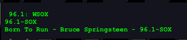
The first is the station code, which (usually) provides the station's call letters and the category of the station's genre, such as Rock, classical, etc. Some stations do not set the genre.
The second is the 8-character field, which for many stations cycles between several items such as the song name, the station catch-phrase, and sometimes the station call letters.
The third is the 64-character field, which music stations often fill with the artist and song information.
RDS information is sent in a very narrow bandwidth, so it is only receivable with a strong WFM signal; and some stations do not transmit RDS, in which case the RDS indicator will be off and no data update will occur.
4.15.2.6 - FM Broadcast Station Spacing
In the US, broadcast WFM stations are assigned frequencies at 100 KHz intervals. Considering that they are allowed to have 150 KHz (or 200 KHz, if broadcasting SCA), this might seem unwise. The way it is made to (usually) work is that in any one region, WFM stations are assigned only even frequencies such as 100.2, 100.4 100.6 and so on, while in regions far enough away, they are assigned only odd frequencies, such as 102.5, 102.7, 102.9 and so on.
This works pretty well at providing 200 KHz between stations in any one area, and will only cause you problems if you attempt to use a high gain antenna and look for distant stations. In that case, you may in fact find them "in between" your more local stations, which can make them pretty hard to pull out, assuming you can hear them at all.
In such a circumstance, 150 KHz is the recommended receive bandwidth unless there are no local stations causing interference. SdrDx's demodulator bandwidth is essentially flat, so don't worry about the demodulator skirts being too tight — exactly 150 KHz will be fine (assuming you're not trying to catch SCA broadcasts, as discussed above.)
4.15.2.7 - Aux Scope Features in WFM mode
Single-channel transmission
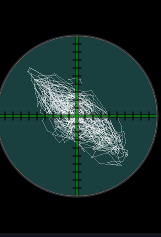
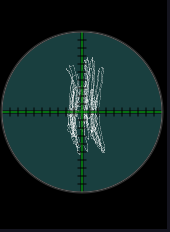
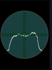
FM Lissajous Display
showing stereo separation
The scope mode provides information about stereo separation. One channel drives the horizontal axis, the other the vertical.
During monophonic reception, when both channels contain exactly the same information, the result is a thin diagonal line.
In stereo, when the channels contain different information, the horizontal and vertical axis are driven differently, and this results in the elliptical patterns similar to those you see on the left.
In stereo, when only one channel has signal, as shown to the right here, then the trace will be primarily horizontal or vertical, depending on the active channel. Divergence from a thin line that the traces show in such a one-channel situation indicate noise or less than perfect channel separation, which is also evident to the right. (That trace is from WQCM's broadcast of the beginning of the Who's "Won't Get Fooled Again.")
Because the frequency response of the X/Y scope goes down to DC, it can also serve as a center tuning indicator. During periods of silence, if the station is correctly center-tuned, the trace will hover about the center of the X/Y scope, directly under the cross-hairs. If you are tuned below the center frequency the station is actually transmitting about, the trace will settle down and right. If you are tuned above the center frequency, the trace will settle up and left. This is also true when there is audio present, however, it is slightly more difficult to see.
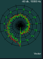
Stereo Spectrum
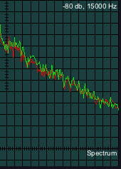
Stereo Spectrum
Stereo Spectrum display: In mode, the scope mode displays both the left and right audio channel spectra, as does the scope mode.
60 KHz FM Carrier
FM Multipath Display
RF Multipath display: When receiving , pressing until it turns to enables a multipath measuring display that is useful for aiming WFM beam antennas.
Because WFM is amplitude across frequency, ideally, the curve you see will be flat. If it isn't, the signal will be distorted. The non-flatness comes from reflections; some signal direct, some off a nearby building. Because these follow paths of different lengths, they are out of phase at the receiving antenna. These time-delayed signals add to the main signal at the antenna in a vector manner, and that gives you phase problems, hence amplitude problems.
When there is no multipath, the waveform should be flat. A gentle curve is preferred to any "s-shaped wiggles" on the trace, which indicate multiple out-of-phase reflections.
4.15.3 - SW Dx'ing
In the international shortwave bands, radio stations are almost always broadcasting at 5 KHz intervals, such as 6,050.000, 6,055.000, and 6,060.000 KHz. Using this interval properly would require the broadcasters to limit their bandwidth to 2500 Hz. They don't, though. So this 5 KHz is so tight that the modulation sidebands from one station actually overlay the sidebands of the next station, creating interference and other audio and RF mayhem.
A good starting point for a crowded shortwave spectrum populated with AM stations misbehaving in this manner is to set the AM bandwidth to 2500 Hz. This cuts off some of the lower frequency (and typically higher power) sidebands from neighboring stations while still capturing a good deal of the audio from the target station. You might want to increase the receive bandwidth to 3 KHz if the station you are listening is more powerful (or has stronger modulation) than the stations next to it.
If the station has no neighbors at 5 KHz intervals, then you can widen the bandwidth to taste without suffering interference. Keep in mind, though, that weaker stations with lower modulation levels also expose you to enhanced noise levels with wider bandwidths. Try it and see.
Often, you will find that AM broadcast signals (both shortwave and down in the AM BCB bands) are too "bassy." Sometimes absurdly so. can help here; try settings around 100 to 200 Hz to cut down on the "muddy" sound.
4.15.4 - Enhancing SW Reception with DX Toolbox
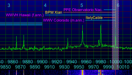
Station identification right there on the spectrum can be provided by DX ToolBox, by Black Cat Systems. It's got a SW database in it that will automatically identify every station transmitting on the frequency you're listening to, at the time you're listening, as you tune. DX ToolBox a great program, offering not only this, but many, many more DXing tools. DX ToolBox is way, way more fun when it's talking to SdrDx, which it does for quite a few of its functions.
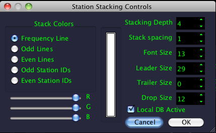
Station Name Controls
You have fine control over this display with a dialog you access with →Right-click .
If you're curious, this feature is achieved via SdrDx's TCP/UDP interface. When you tune around in SdrDx, DX ToolBox sends a label command which contains information about known stations presently transmitting on that frequency.
DX ToolBox uses a database for this, and provides a very easy means for you to keep that database updated — just a click of a button does it.
in addition to the station names, in the DX ToolBox window itself, the station's transmitting location, country of ownership, and the region it is targeting with its transmission are shown as well, along with the station's scheduled airtime.
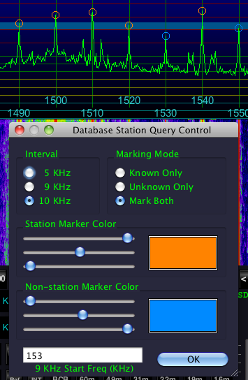
Database Station Query Control dialog
At the left, the Database Station Query Control dialog, accessed by →Right-click - sets the colors, band spacing, starting frequency for 9 KHz offset station assignments, and marking conditions.
When DX ToolBox is connected to SdrDx, if you →Left-click , SdrDx and DX ToolBox will work together to identify each frequency in the visible span that has a known station broadcasting at the moment.
If you select the Known Only radio button, SdrDx will only mark station intervals where the DX ToolBox database indicates there is a known station active at the moment. If you select the Unknown Only radio button, SdrDx will only mark station intervals that are not known to have a station on them at the moment. If you select the Mark Both radio button, SdrDx will mark all station intervals within the current span.
The two colors in the dialog are used for the two different kinds of markers, known and unknown. In the image to the left, you can see that 1,530.000 and 1,550.000 are not known to the database, while the other intervals do have database entries.
You can use to quickly identify stations that are new or unknown, including pirate stations. You can use it to identify stations you can assign using SdrDx/s companion SwDb tool. For instance, I DX the US AM broadcast band. I have identified most of the stations I usually hear using SwDb, but there are a few yet to go, particularly in the graveyard frequencies. →Left-click quickly shows me which ones I need to work on getting an ID on. You can also use it to identify places where stations are on the air, but you can't hear them because of conditions or antenna orientation; if you can re-orient your antenna, there's a chance you might hear these stations. Likewise, propagation may change so perhaps a little patience will yield results.
blinks while it is setting up the markers for you. Remember that it only works if DX ToolBox is connected to SdrDx. DX ToolBox provides the data it needs from its database, and from the SwDb database.
DX ToolBox is very useful. My highest recommendation.
Also relevant to SW listening and DXing, see the AM Broadcasting band DXing section, next, for some information about C-QUAM stereo broadcasts. This information applies 100% to shortwave operation.
4.15.5 - AM broadcast band DX'ing
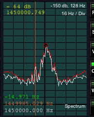
1450 KHz
Graveyard Frequency
In the US AM broadcast band, stations are spaced 10 KHz apart. Because of this, you can safely use much wider bandwidths than are practical in the shortwave bands. An excellent starting choice is 5 KHz. In other regions, you may be working with AM Broadcast band spacings of 9 KHz; in this case, try using 4.5 KHz as the receive bandwidth.
If you are lucky enough to live in a location where you can hear both US and European stations in the AM BCB band, you'll enjoy some great DX'ing, but I don't really have any advice other than deal with each station as circumstances require. Mixing 9 KHz and 10 KHz station placement results in kind of a mess!
While AM band DXing, try setting the scope to mode, with the CAR Span control set to 11 o'clock, which is 16 Hz per horizontal division. At this setting, you can see multiple carriers when you are receiving multiple stations. A left-click on the scope will mark any carrier frequency you are interested in. This can be very revealing, particularly on the "graveyard" channels of 1230, 1240, 1340, 1400, 1450 and 1490 KHz.
You might also try turning on , the peak-hold function.
Often, you will find that AM broadcast signals (both shortwave and down in the AM BCB bands) are too "bassy." can help here; try settings around 100 to 200 Hz to cut down on the "muddy" sound.
4.15.5.1 - C-QUAM AM Stereo
There are AM-format BCB and SW broadcasts using C-QUAM stereo encoding. SdrDx can decode these this way:
- →Left-click
- Adjust demodulator bandwidth on Spectrum to be symmetrical
- Tune to station
- →Left-click
You can →Right-click to access phase-reversal and left-right channel swap options for the C-QUAM decoder.
As stereo decoding in C-QUAM is generally more noisy than mono for some of the same reasons that WFM stereo is, you will likely find both and useful with weaker stations.
The following stations are reported to be broadcasting in C-QUAM stereo in late 2016:
- 540 WXYG, Sauk Rapids, MN, US
- 740 WDGY, St Paul, MN, US
- 540 Ga-Rankuwa, South Africa
- 576 Meyerton, South Africa
- 864 Paris, France
- 954 Sidvokodvo, Swaziland
- 1485 Rome, Italy
- 1584 Somewhere, in Italy
- 1098 Ga-Rankuwa, South Africa
- 41m pirate X-FM Somewhere in the US
Also check this page for US AM BCB stations that may still be broadcasting C-QUAM.
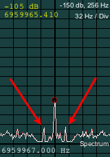
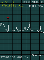
C-QUAM Pilot at 25 Hz
You might be thinking, "How do I know if an AM station is broadcasting in C-QUAM?" With some stations, you can see a 25 Hz pilot tone on the signal using the auxillary scope mode when CAR Span is set to 32 Hz/Div, as shown at the right. If you see those two spikes at 25 Hz, the station is definitely broadcasting C-QUAM.
However, not all stations that are broadcasting in C-QUAM transmit the 25 Hz pilot tone, so not seeing the 25 Hz pilot doesn't prove the station isn't broadcasting in C-QUAM. That, by the way, is why SdrDx doesn't try to auto-detect C-QUAM; it wouldn't always work.
4.15.6 - Longwave BCB (153-270 KHz) and Euro MW BCB Reception
If you have an SDR that can go 180 KHz wide or wider, here's how to set up for LW reception:
- Set the SDR bandwidth to 180 KHz or wider using the dialog
- Set the Span to 180 KHz using and/or
- →Left-clickGS and set to 20
- Center tune to 216.000 KHz
- Click on the 180 KHz channel (because of 10 KHz std AM spacing)
- Use the +/- 9 KHz center and demodulator tuning keys to tune (key functions 384, 385, 301 and 300)
Now you can use the 9 KHz up and down key functions to shift up or down by 9 KHz on either the center tune or the demodulator (the channel spacing here) wherever you see an AM carrier. This same setup can be used with European MW BCB stations, which are also spaced at 9 KHz.
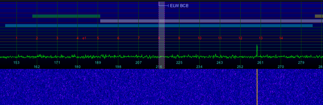
SdrDx set up for longwave BCB reception
4.15.7 - CW reception
One thing to watch out for when listening to CW is the low-level heterodyne at the center frequency. It's always there, and so it can interfere with your listening. So let's say you want to monitor 21,150.000 for the CW beacon network that resides there. Rather than tune the SDR center frequency to 21,150.000, tune it to 21,140.000, and then tune the demodulator frequency (top value) to 21,150.000. This way, the interference is at 21,140.000, completely out of your way. This is good advice for any mode: don't include the center frequency in the audible portion of the passband, or you'll end up having to deal with that heterodyne (if you must deal with it, use an audio notch.)
Generally speaking, adjust the demodulator frequency to the exact center frequency of the CW signal you're interested in. Set CWO to 700 Hz (or whatever tone pleases you) and then narrow the demodulator bandwidth to +/- 200 Hz or so. Fine adjustment of CWO is available via ^ PageUp and ^ PageDown.
4.15.8 - SSB Reception
Typical SSB signal spacings in the amateur bands are about 3 KHz. Consequently, 2.9 KHz is a good starting demodulator width unless you're experiencing interference. Below 10 MHz, amateur stations typically use LSB; above 10 MHz, USB. One exception to this is in the 5 MHz region (60 meter band), where USB is required by international telecommunications treaty. In many cases, it isn't a bad idea to pull up the lower edge of the demodulator to 100 or 200 Hz, either.
As an interesting side note, some modern transceivers can transmit using bandwidths much wider than 3 KHz, so watch the indicated bandwidth on the spectrum and waterfall, and if there isn't any interference, take a listen with the demodulator bandwidth more open than usual. Audio quality can be surprisingly good.
4.15.8.1 - Splatter
Poorly adjusted (or defective) transceivers (and/or amplifiers, tuners, antennas, switches, feedlines and connectors) can results in emissions of RF outside of the intended design bandwidth. This is known as "splatter." Splatter shows up as RF that is obviously outside the normal transmit bandwidth for a signal. For instance, you may be able to see that the transmit audio for an SSB station is about 3 KHz wide, but that above and below this, when the station operator is sending audio, additional RF appears to the left and right of the 3 KHz bandwidth.
But before you assume someone is splattering, make certain you look at their signal with the noise blanker off. The noise blanker removes anything that matches the threshold criteria, for the width it is set to. This in turn can alter the RF waveform so that aliasing of correct waveforms occurs, and that in turn results in "ghost" signals appearing where they actually do not exist in the RF display. Basically, if the noise blanker is on, you can easily misidentify noise blanker artifacts as splatter.
4.15.9 - FM Reception
FM transmits information by swinging the carrier frequency away from the carrier center in both directions. How far it swings encodes the amplitude of the signal, and how fast it swings communicates the frequency of the signal it is carrying.
Because of this, if you have then demodulator bandwidth set too narrow, the resulting demodulation will be clipped, resulting in flat-topped, unpleasant distortion. So pay attention to the spectrum and set the bandwidth according to the observed bandwidth, not any assumption about what the bandwidth is supposed to be. For instance, a lot of communications equipment is assigned a bandwidth of 5 KHz; however, that doesn't mean the equipment is, in fact, transmitting only 5 KHz wide. I have observed many commercial signals that are assigned a 5 KHz channel width that are actually transmitting as wide as 10 KHz. They're probably overdriving the transmitter (remember, amplitude is directly related to transmit bandwidth) on an older transmitter — or a poorly designed one that doesn't properly limit the audio amplitude. I've seen unusual bandwidths in the case of some Amateur radio signals on 10 meters as well.
Make sure you don't have the VOL setting too high. Some OS X machines, for instance, have output audio systems that can distort even with undistorted high level audio produced by SdrDx. One audio product that has demonstrated this is the "iMic"; with SdrDx's VOL set to 99, the "iMic" distorts fairly badly.
| toc | index | guide | changes | keyboard | , previous | . next |